How To Use Path Lookup
Unicast Path Lookup
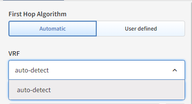
First Hop Algorithm And VRF
First Hop Algorithm adds possibility to start path lookup simulation from a different device than the closest one.
If Automatic option is selected, IP Fabric starts path lookup simulation from the closest device possible, VRF is also automatically selected by default, but can be changed manually.
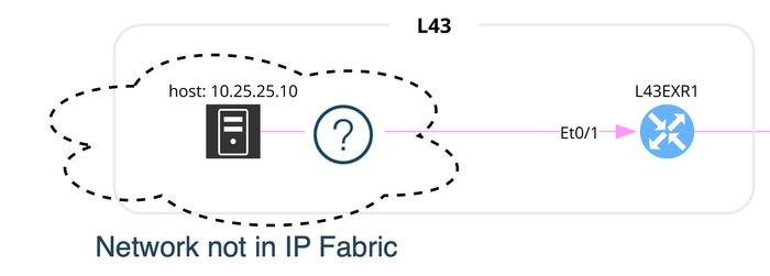
User defined First Hop Algorithm can be useful when simulating flow where the source network is not known by IP Fabric.
To simulate such flow, it is necessary to specify the starting point by entering the name of the device and the interface which will be used to start the path lookup.
Packets will use the source IP indicated.
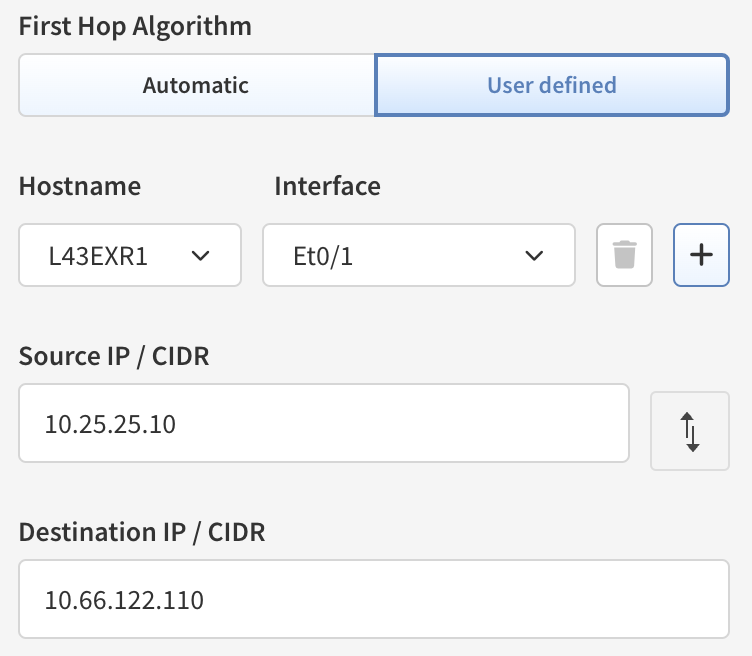
User Defined First Hop Algorithm
In the example below, the source network 10.25.25.0/24 is not known by IP Fabric. To show the path between a client in this network and a server in a network known by IP Fabric:
- Select
User DefinedFirst Hop Algorithm - Search for the device where to start the path:
L43EXR1 - Select the source interface:
Et0/1 - Enter the source IP, from the network outside the scope of IP Fabric:
10.25.25.10 - Finally enter the destination IP:
10.66.122.110
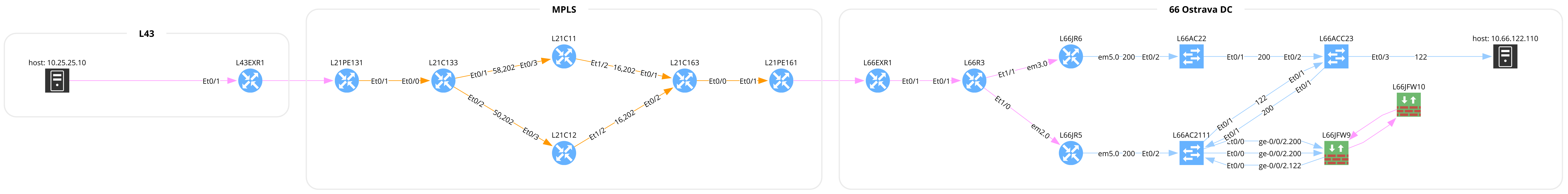
This is the result you will get:
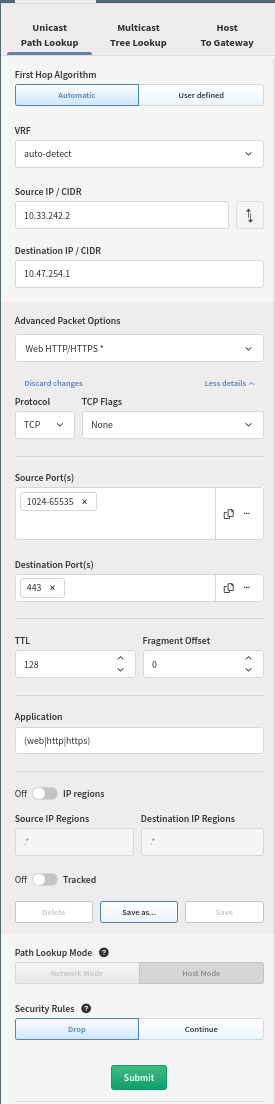
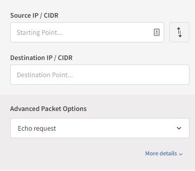
Source/Destination IP Address and Port
As a source/destination IP address can be used a plain IP address or a CIDR (Classless Inter-Domain Routing) when for example simulating path lookup from a host to a network.
By default, ICMP protocol and Echo request is chosen for path lookup.
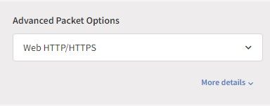
When switched to Web HTTP/HTTPS, TCP destination port 80 and 443 with (web|http|https) application is set by default.
When extending details, transport protocol and range of ports can be specified for a source and for a destination. When more destination ports are specified, IP Fabric will analyze all of them individually during the pathlookup.
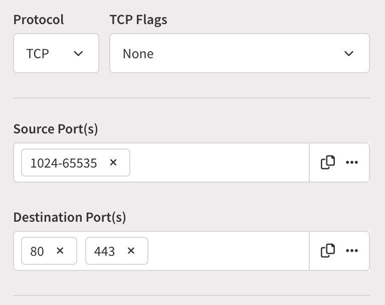
Port can be changed to an arbitrary one for TCP/UDP protocols.
The following flags can be also set for TCP traffic – None/ACK/FIN/SYN/RST/PSH/URG.
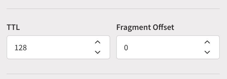
TTL and Fragment Offset
In More details, TTL (Time to live ) and Fragment offset can be set - thus affecting path lookup output - default TTL is 128 and Fragment offset is set to 0
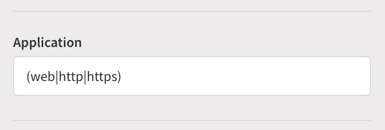
Application
When evaluating security rules and security appliances on the path check traffic on L7, an application can be checked on the path lookup.
It’s almost impossible to standardize application names across all vendors. You can define your own application name with regular expressions.
Info
An application name input is just a string, so it needs to be defined exactly as in a security rule!
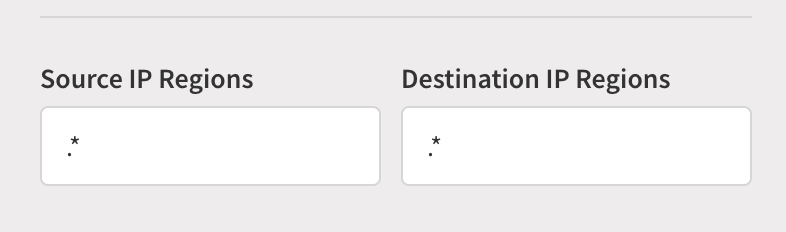
Source/Destination IP Regions
When testing access to or from the internet, source or destination IP regions can be set.
Example: Europe, China, etc.
By default IP regions are not evaluated.
Info
IP regions are just a string, so they need to be defined exactly as they are in a security rule!
Path Lookup Mode
If you’ve used a network CIDR instead of a single IP address, you will have the option between:
- Network Mode – simulation starts and ends with whole networks, individual hosts are not considered
- Host Mode – simulation starts and ends with each host. It is limited to 255 hosts, source and destination combined.
Then click on submit.
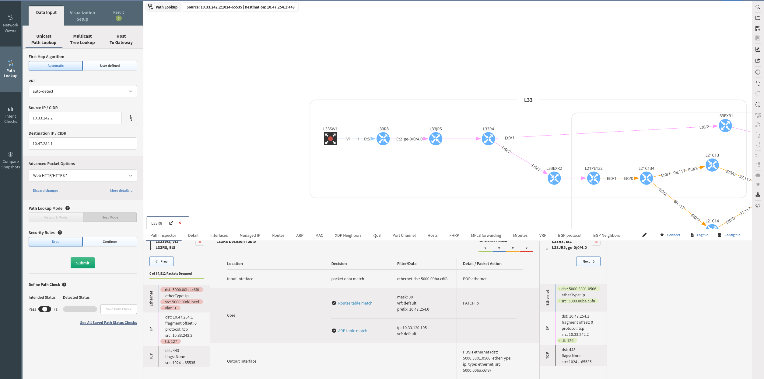
This is how path lookup might look like:

Security Rules
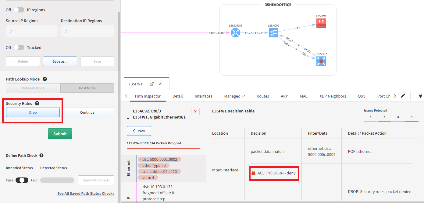
If Drop is selected the path lookup will stop when a security rule denies traffic.
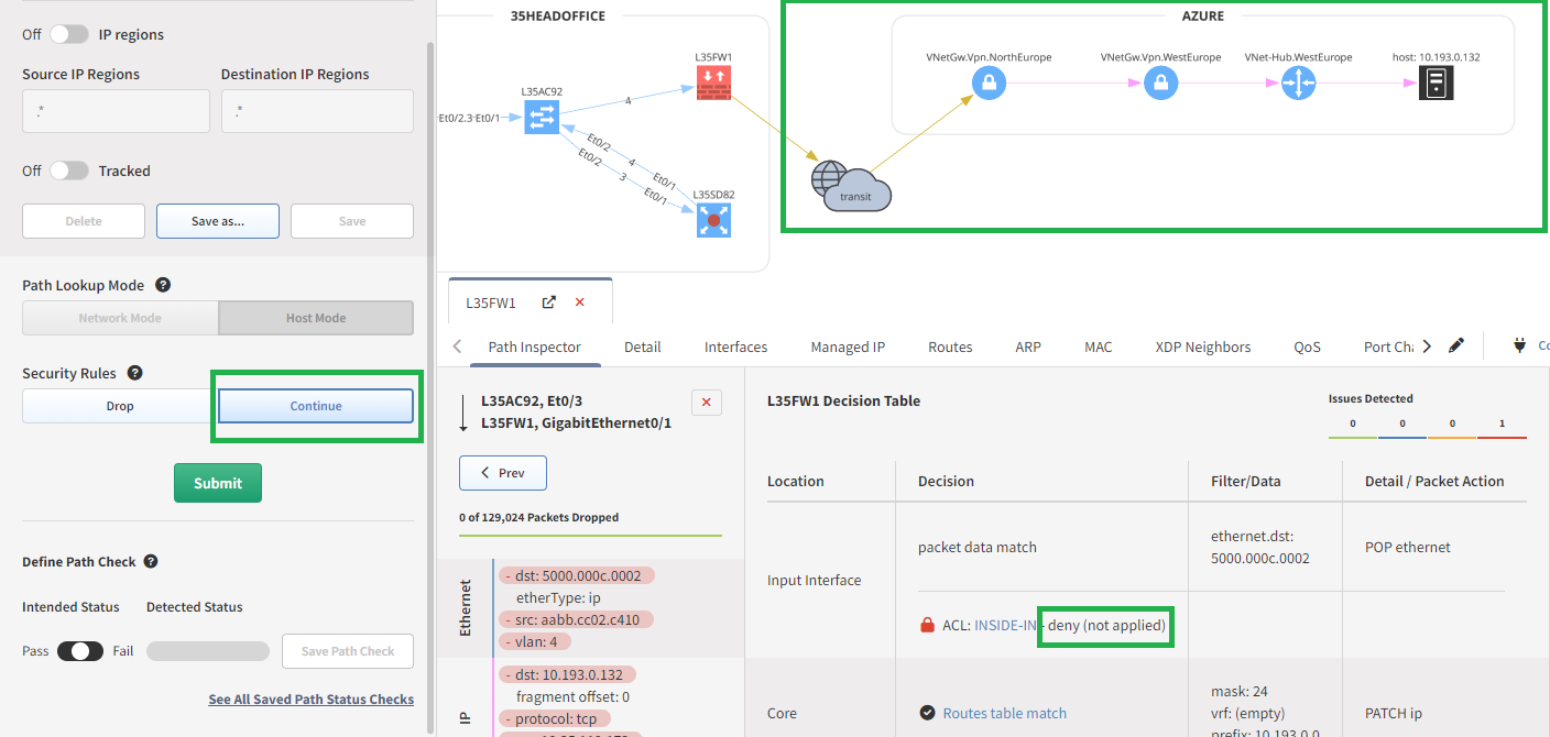
If Continue is selected the path lookup continues and does not apply the
policy’s deny; in the detail pane it is labeled as (not applied).
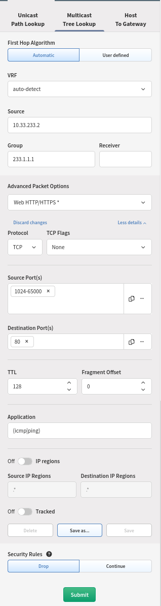
Multicast Tree Lookup
You want to understand how a certain multicast flow is used, you can use the Multicast Tree Lookup. For that, just select the correct option and enter the relevant details
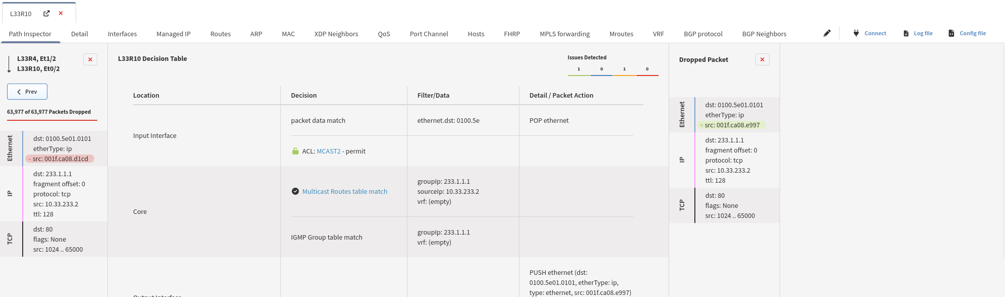
You will then see the Multicast Tree:
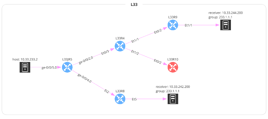
And you will have access to a lot of information regarding the Multicast forwarding decision:
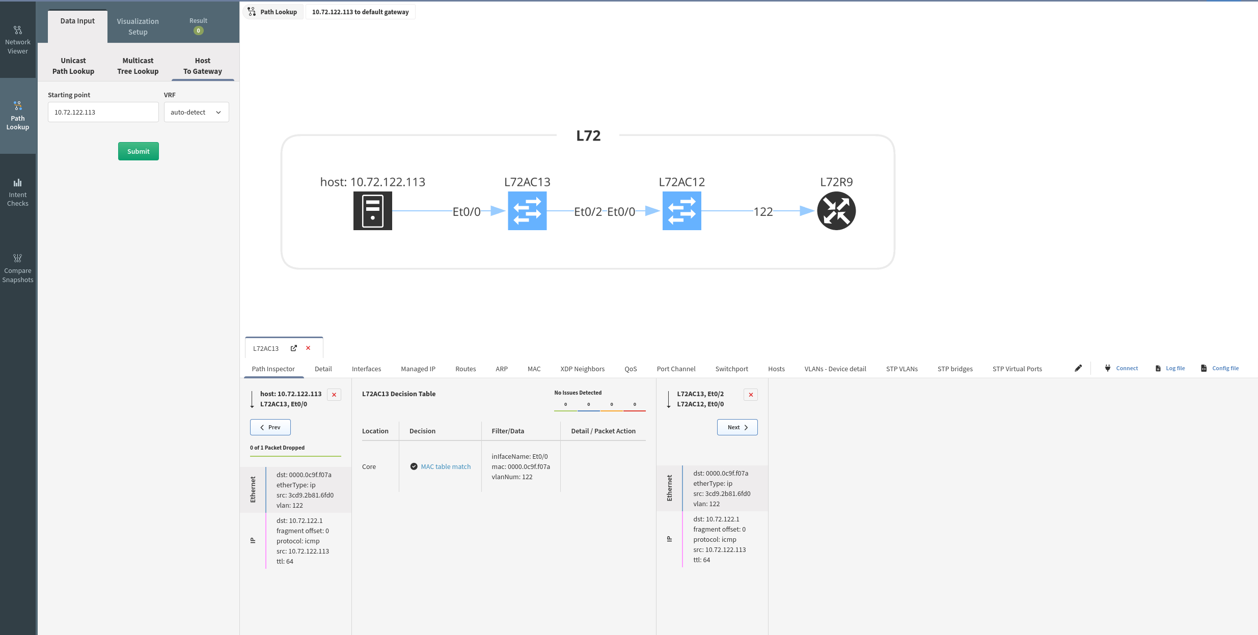
Host To Gateway
To find out more details between a host and its network gateway, you can use this menu: Host To Gateway. You only need to provide the host, and you will the details:
Inspecting And Adjusting Path Lookup
Path Controls
With the mouse right-click, more options are enabled:
After opening the details, we can select the destination link to proceed with packet analysis:
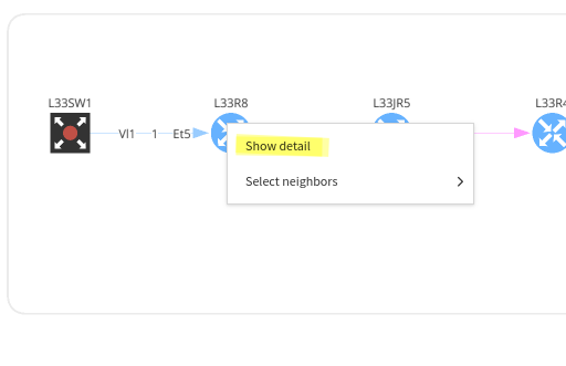
Understand The Path Selection
To understand the decision taken by a device, right-click on the device and “show detail”. You will then be presented with the details. If you have more than one interface where the flow can come from, you will need to select the interface you want to look at. Similarly, if you have several interfaces that can be used to forward the traffic, you will have to choose one. Then in the middle of the table, you will see the forwarding decision:
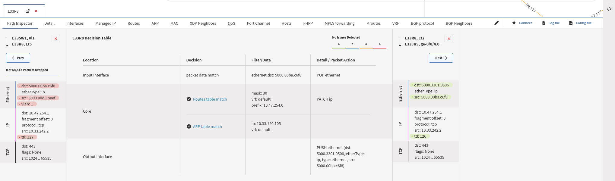
In this example, we are looking at the device L21C11, which has 2 incoming interfaces and one forwarding for this flow:
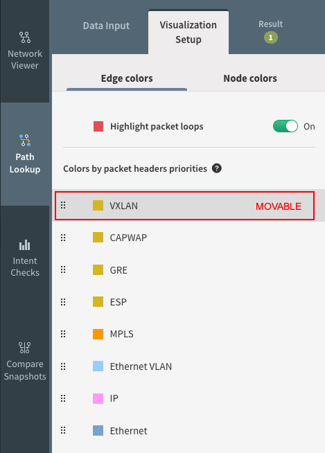
Visualization Setup
You can set up what you want to prioritize in the view. Just simply move the bars up or down.