Network Viewer
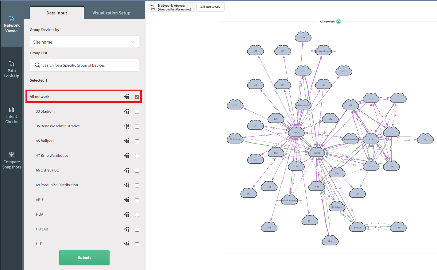
When you go to the page Diagrams → Network, all networks are displayed and the relationships between them. They are grouped into sites represented by a cloud for better visibility. You can double-click on a cloud to explore further that specific site.
Top-level view with all network:
Adding Networks To The View
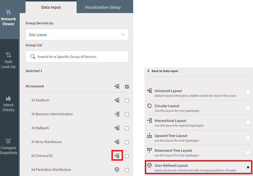
To display the required information, select on the left side the site you want to visualize and click on Submit.
One or more sites can be displayed at a time.
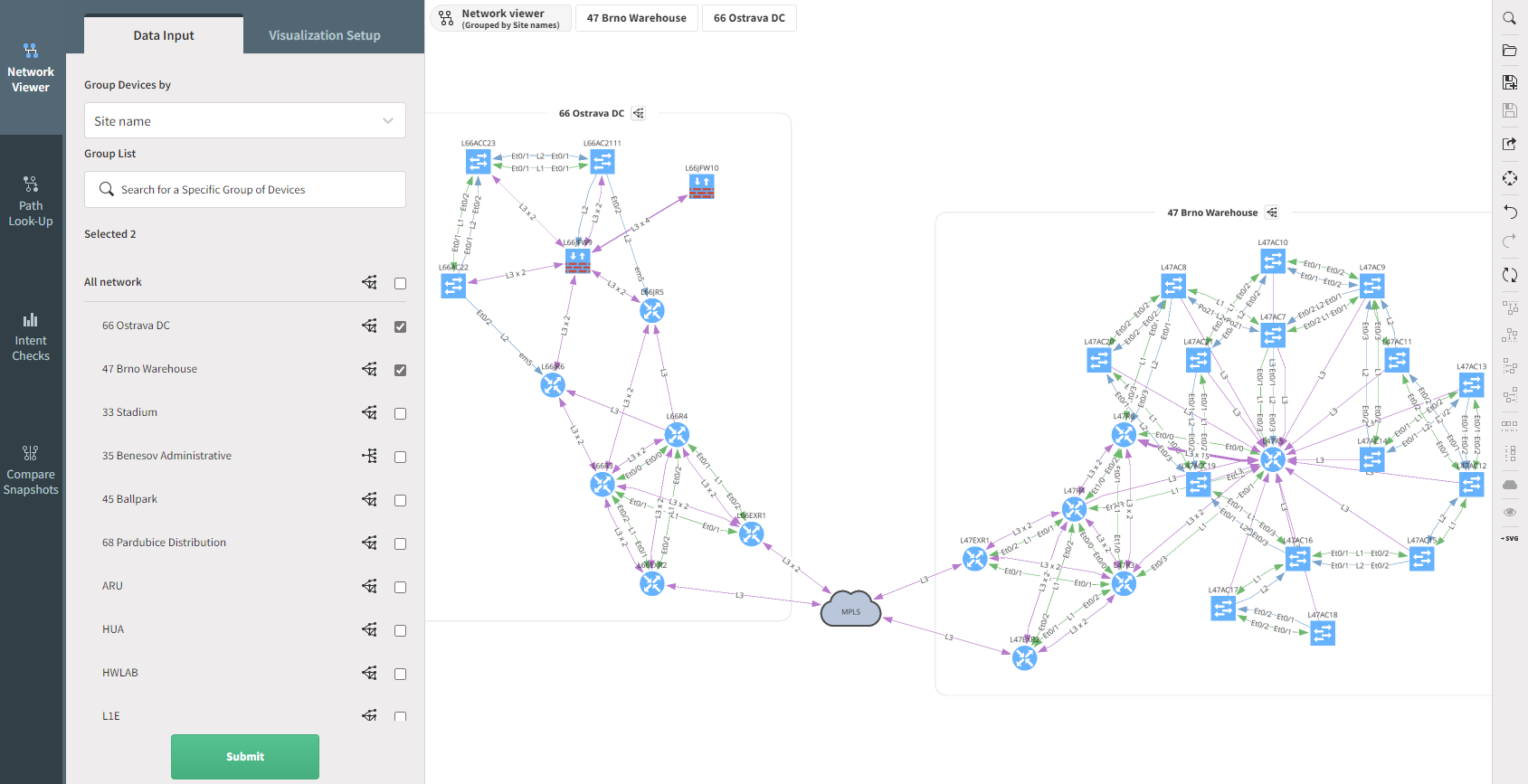
For example, to see a diagram of particular sites called 66 Ostrava DC
and 47 Brno Warehouse:
-
Select Site name from Group Devices by drop-down menu
-
Select the site names
-
Click Submit
Removing Networks
In a very similar way as to add a site/network to a diagram, to hide it, just unselect the network and click Submit.
Manipulating Objects And Nodes
Diagrams are generated automatically, and the following supported operations can change their layout:
- Pinch to zoom: touch & desktop (if supported by the trackpad)
- Mouse wheel to zoom: desktop
- Two-finger trackpad up or down to zoom: desktop
- Tap to select: touch & desktop
- Tap background to deselect: desktop
- Multiple selections via modifier key (shift, command, control, alt) + tap: desktop
- Box selection: touch (three-finger swipe) & desktop (modifier key + mouse down then drag)
- Grab and drag nodes: touch & desktop
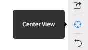
The Center View button can also center the screen view.
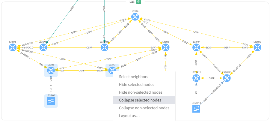
Hide/Collapse Items In The View
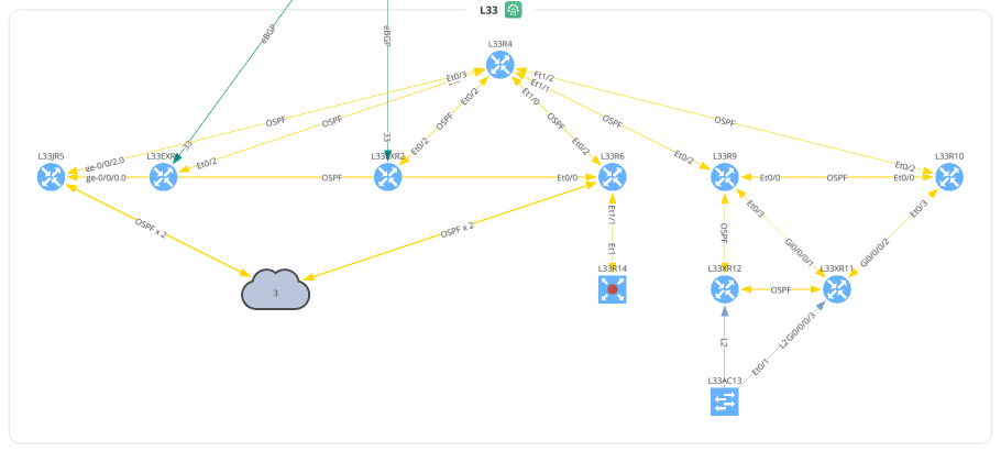
After selecting a set of devices, or cloud, if you do a right-click, you have the option to collapse the selected items into a new cloud, or hide them:
Layouts
Save User-defined Layout
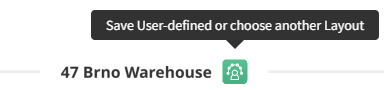
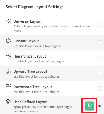
After editing the layout, you will see the green box, this allows you to save the changes as the default view. Click on the green box, this will open a menu Select Diagram Layout Settings and the last entry is the User-Defined Layout. By clicking on the floppy disk icon you will update the default view (see below). Please, be aware that only position of the visible nodes will be saved.
Use User-defined Layout As The Default Layout
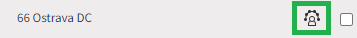
Once you have created a user-defined layout, you probably want to use this as the default layout. For this, click on the icon of the site you want to update, then select the User-Defined layout and click Save
From now on, this will be the default layout for this site:
Choose a Specific Layout For a Selection Of Devices
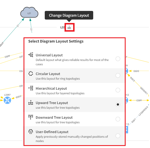
You can now specify which layout you want to use for a set of devices:
Choose a Layout To Apply For The Whole Site
Similarly, you can select a layout for the whole site, using the layout selection.
- Circular Layout can be used only for 500 nodes or less.
Save, Load, And Share View
Each object can have multiple views that can be saved and loaded again later.
Save View
Click the floppy icon on the menu on the right end side:
Enter a name for that view and click save.
Info
The view saved in this way is not the default view for that object.
Load View
The view can be loaded by clicking the folder icon.
Select the desired view and click to load.
Share View
By clicking here, an URL will be displayed, which you can share with other users, and they will be able to see this view.
Export Current View To SVG/PNG
The view can be exported in the form of a SVG or PNG image by clicking on Export and selecting the format you want
Info
The SVG file can be imported into a Visio diagram, or on other drawing application
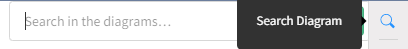
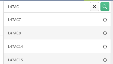
Search
Search looks up any text currently present on the diagram. Typing query filters the view and clicking on the search button focuses and zooms in on the item.
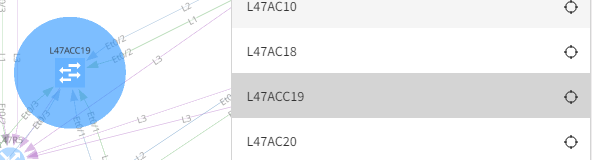
If you hover your mouse on one entry, you will see the device on the diagram:
Protocols
The user can filter connection protocols between devices of the second and third layer of ISO OSI by using filters in the Network Viewer / Visualization Setup / Protocols menu.
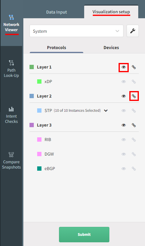
You can decide which layer/protocol you want to display/hide and group/ungroup
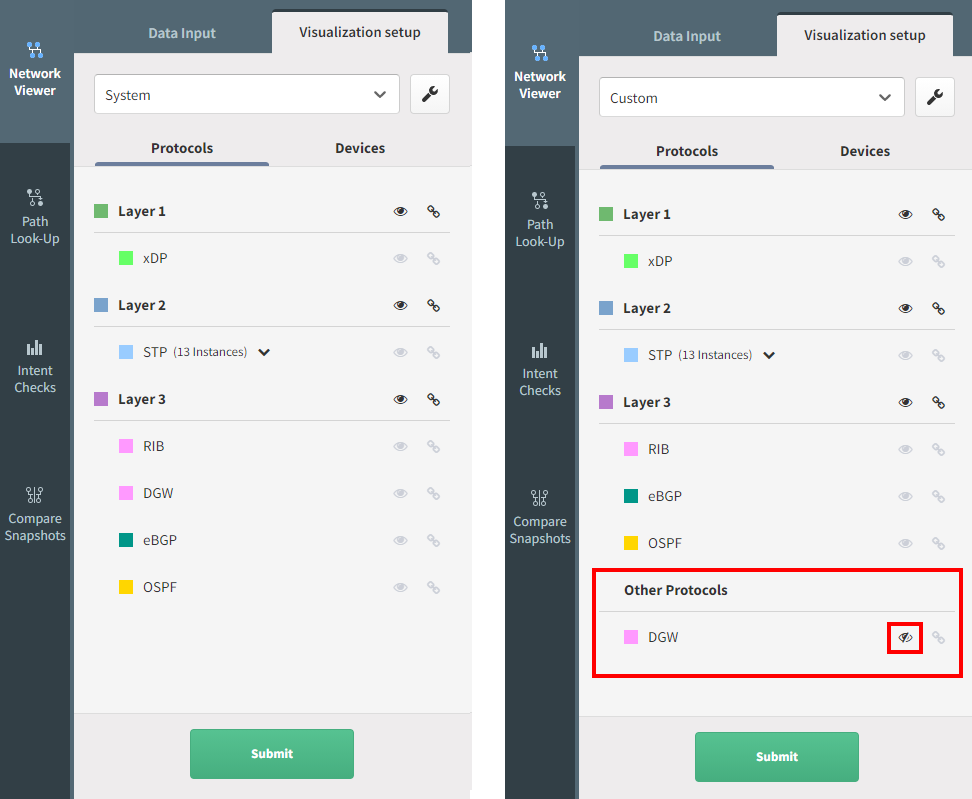
Default Protocols View
By default, all discovered protocols will be grouped based on the layer they belong to. This is the System view. You can edit this, which means you are able to ungroup certain protocols. For this click on the Settings icon:

Drag and drop protocols you want to put to a custom group to the Other Protocols, click on Save as and give a name to the new protocol view.
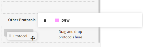
With the example below, you are now able to hide only the DGW protocol, without affecting the other Layer3 protocols:
Link grouping
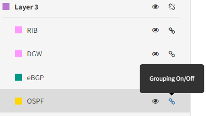
Link grouping means that protocols of the specific layer are not shown as separate lines but together as a single line.
Layer Grouping
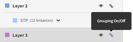
Layer Grouping collapses groups of devices according to the types of links that connect these, either in Layer 2 or 3 groups. Devices connected with different layer protocols can’t be grouped together.
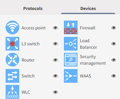
Devices
You can select/un-select the type o devices you want to see on the diagram.
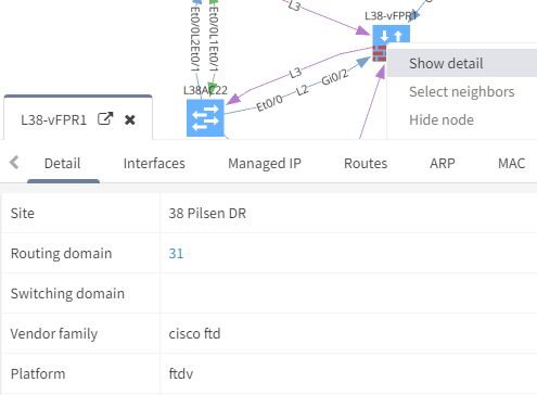
Device Information Deep Dive
After right-clicking on the device, it is possible to display additional information about it by selecting Show detail: